What is GPON technology and how it works: technical secrets
GPON stands for Gigabit Passive Optical Network , the alternative to Ethernet switching in campus networks. GPON Replaces Traditional Three-Tier Ethernet Design through a two-tier optical network by eliminating access and distribution Ethernet switches with passive optical devices. Today in RedesZone we are going to reveal to you all the technical secrets of this technology, which all fiber optic operators in Spain use to bring fiber optic internet connection to the homes of all their customers.
We will start by explaining a series of concepts that will help us better understand how this technology works.
GPON network terminology
GPON networks are made up of different equipments to realize the connection to the network and to the Internet via optical fiber, knowing what each equipment is and what it is used for is very important, then you can read in detail all the equipment with which it is used it works when talking about GPON.
- Gigabit-Capable Passive Optical Network (GPON) : Standard for Passive Optical Networks (PON) published by ITU-T.
- Optical distribution network (ODN) : These are the physical fiber optic devices that distribute signals to users in a telecommunications network. The ODN is made up of passive optical components (POS), such as optical fibers, and one or more passive optical splitters.
- Optical Network Termination (ONT) / Optical Network Units (ONU) : These are the devices that are installed at the end users (office, telephones, etc.) to connect to the GPON network. They convert the optical signal into an electrical signal. ONTs also provide AES encryption via the ONT key.
- Separators - Used to add or multiplex fiber optic signals to a single upstream fiber optic cable. In general, the most used ratio is 1:32.
- Optical Line Terminal (OLT) : A device that aggregates all optical signals from ONTs into a single multiplexed light beam which is then converted into an electrical signal, formatted to Ethernet TPE packet standards for Layer 2 or Layer 3 transfer.
- Wavelength Division Multiplexing (WDM) : The division multiplexing Wavelength (WDM) is a technology that multiplexes multiple optical carrier signals onto a single optical fiber using different wavelengths (i.e. colors) of light.
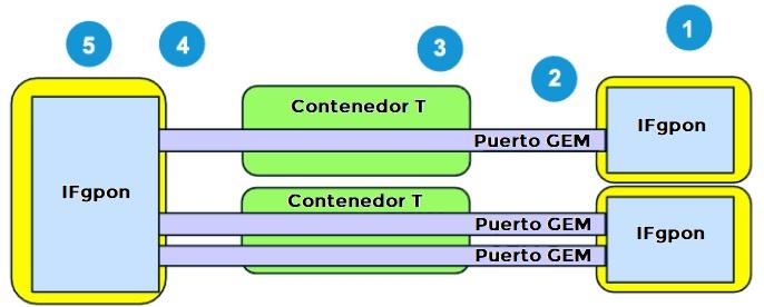
- GEM G-PON (GEM) Encapsulation Method : This is a data frame transport scheme used in gigabit capacity Passive Optical Networking (G-PON) systems that is connection oriented and supports data frame fragmentation. variable size.
- Fiber to the X (FTTX) : FTTX is a generalization for different fiber deployment configurations, organized into two groups: FTTP / FTTH / FTTB (Fiber laid to the end of the premises / house / building) and FTTC / N (fiber laid to the cabinet / node, with copper wires to complete the connection).
- T-CONT / TCONT : This is the transmission container.
- OMCC : It is the control and management channel of optical network units.
- IMCO : This is the control and management interface of the optical network unit.
- PCBd : This is the downstream physical control block.
- CT : This is time multiplexing.
- TDMA : Multiple access by distribution in the time.
Network diagram
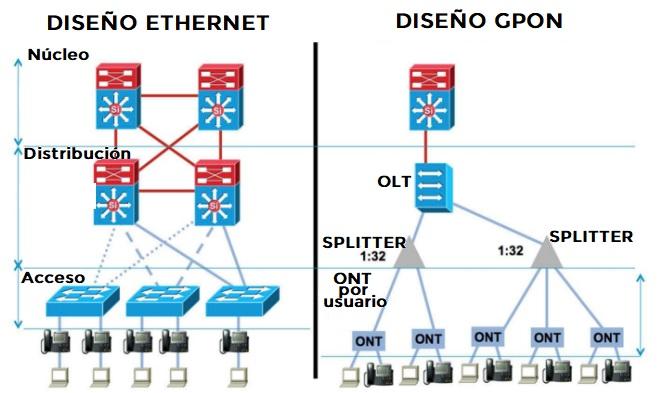
In the popular Ethernet design we have three main levels, the core or the core where the L3 equipment is located, they are interconnected with each other and provide redundancy using internal gateway dynamic routing protocols such as OSPF, as well as protocols such as VRRP. The distribution level is also made up of L3 and L2 equipments, and finally we have the access layer, which are the equipments to which the final equipment will be connected, such as computers, WiFi access points, telephones IP and others.
In the GPON design we will find a total of two levels, the OLT is one of the most important parts because it will be the one used to interconnect the different equipment, we also have 1:32 distributors that allow us to subdivide the fiber to connect more users simultaneously and, finally, we have an ONT for each of the users. Of course, all of these devices are passive, as the name "GPON" suggests.
As you have seen, the GPON design is very simple but powerful, a good example is that it will allow us to achieve high speeds on the network thanks to the fiber, in addition, it is very cheap because electricity consumption is minimal.
Technology overview
First, the OLT is connected to the optical splitter through a single optical fiber, then the optical splitter will be connected to the ONU / ONT. Then GPON will adopt WDM to transmit data of different upstream / downstream wavelengths on the same ODN. The wavelengths will be between 1290 and 1330 nm in the upstream direction and between 1480 and 1500 nm in the direction of discharge. It will start data transmission in the download direction and in turn burst mode, download in TDMA mode (based on time interval). Finally, point-to-multipoint (P2MP) multicast transmission will be supported.
GPON technology features
GPON technology has been around for years, giving us very high upload and download speeds in our homes, even though we are a long way from the main OLT our encryption branch connects to. We are now going to see the main features of GPON, so that you can see its limits and power consumption.
GPON limits
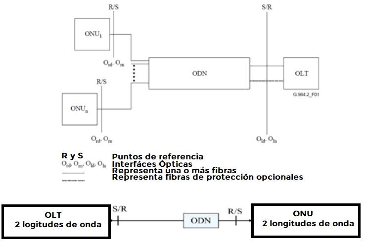
- Maximum logical range: 60 km (this is the maximum distance managed by the upper layers of the system (MAC, TC, Ranging), in view of a future specification dependent on physical media (PMD)).
- Maximum fiber distance between transmit / receive (S / R) and receive / transmit (R / S) points: 20 km.
- Maximum differential fiber distance: 20 km.
- Division ratio: limited route loss, PON with passive distributors (16, 32 or 64 lane separation).
- Speed: 1,24416 Gbit / s download, 2,48832 Gbit / s download.
Energy budget
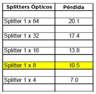
In the context of GPON, the loss of optical power must be taken into account. This loss can be introduced in different ways, such as:
- Loss in dividers.
- Loss per km of fiber (approximately 0,35 dB per km for 1310 and 1490 nm).
- Splice loss (> 0,2 dB).
- Bending of fibers.
As the picture shows, the amount of loss incurred when using multiple dividers:
As the picture shows, the minimum and maximum optical path loss per class:
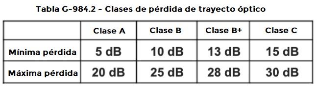
NOTE: The requirements of a particular class may be more stringent for one type of system than another, e.g. ex. Class C attenuation range is inherently narrower for the TCM system due to the use of a 1: 2 splitter / combiner on each side of the ODN, each with approximately 3dB loss.
How packet forwarding works in GPON technology
Downstream packet path (from OLT to ONT)
Package ride downstream. As shown in the picture, the packets go downstream from the OLT to various ONUs or ONTs.
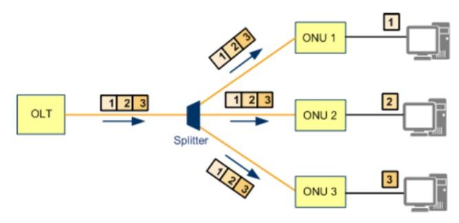 Tip to understand the diagram: The downstream flow is from the point of view of the splitter, it can be thought of as traffic directed to the ONU / ONT, or the end users.
Downstream packets are transmitted as transmissions, with the same data sent to the same ONU / ONT with different data identified by the GEM port ID. Allows an ONU / ONT to receive the data desired by ONU ID. The wavelength range for discharge is 1480 to 1500 nm. Continuous mode operation in the direction of discharge - even when there is no user traffic via GPON, there is a constant signal except when the laser is administratively disabled.
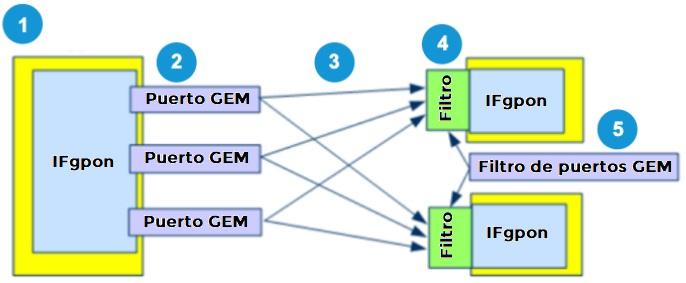
As shown in the picture, the downstream packet transfer procedure.
Communication process
- The OLT sends Ethernet frames from the uplink ports to the policy-based GPON service processing module configured for the PON ports.
- The GPON service processing module encapsulates Ethernet frames in GEM port data packets for downstream transmission.
- GPON Transmission Convergence (GTC) frames containing GEM PDUs are transmitted to all ONT / ONUs connected to the GPON port.
- The ONT / ONU filters the received data based on the GEM port ID contained in the header of the GEM PDU and only retains meaningful data for GEM ports in that ONT / ONU.
- The ONT decapsulates the data and sends the Ethernet frames to end users through the service ports.
Downstream packet frame structure
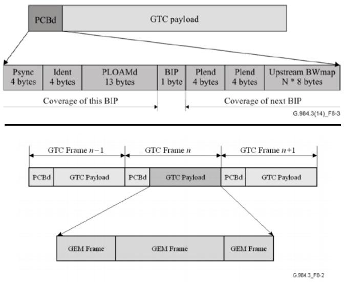
A GPON frame in the discharge direction has a fixed length of 125 s, made up of two components: the physical control block in the discharge direction (PCBd) and the payload. The OLT transmits PCBd to all ONUs / ONTs. The ONUs / ONTs receive the PCBd and perform operations based on the information received. PCBd consists of a GTC header and a BWmap
- GTC header - Used for frame delineation, synchronization and forward error correction (FEC).
- BWmap: the field informs the ONU itself of the uplink bandwidth allocation. Specify the start and end ascending time intervals for the T-CONTs of each ONU, this ensures that all ONUs send data based on the time intervals specified by the OLT to avoid data conflicts.
As shown in the picture, an enlarged view of the PCBd and what is in the GTC payload.
Keywords
- Psync (4 bytes long): physical synchronization field, indicates the start of each PCBd.
- ID (4 bytes long): used to indicate larger frame structures, contains the super frame counter used by the encryption system.
- PLOAMd (13 bytes long) - Field downstream of the OAM Physical Layer (PLOAM), think of this as a message-based management and operation channel between the OLT and the ONU / ONT.
- BIP (1 byte in length): parity of interleaved bits, by the receiver to measure the number of errors in the link.
- Full (4 bytes long) - Decreasing field for the length of the payload.
Upstream packet path (from ONT to OLT)
As shown in the picture, the upstream packet flow from multiple ONUs to the OLT.
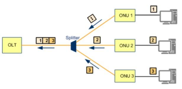 Tip for understanding the pattern: You can think upstream from the dispatcher's point of view, or the traffic sent from the UNO / ONT, end users to the OLT.
Upstream packet transmission is via TDMA (Time Division Multiple Access). The distance between OLT and ONT / ONU is measured. The slots are allocated based on the distance ONT / ONU sends the uplink traffic based on the allocated time slot. Dynamic Bandwidth Allocation (DBA) allows the OLT to monitor congestion, bandwidth usage, and configuration in real time. Detects and prevents collisions all over the range. The wavelength in the upstream direction ranges from 1290 to 1330 nm. As shown in the picture, the upstream packet transfer procedure.
Communication process
- ONT / ONU sends Ethernet frames to GEM ports according to configured rules that map service ports and GEM ports.
- GEM ports encapsulate Ethernet frames in GEM PDUs and add these PDUs to TCONT queues according to the rules that allocate GEM ports and TCONT queues.
- TCONT queues use DBA-based time slots and then pass the upstream GEM PDUs to the OLT.
- OLT decapsulates the GEM PDU, the original Ethernet frame is now visible.
- OLT sends Ethernet frames from a specified uplink port according to the rules that assign service ports and uplink ports.
Upstream packet frame structure
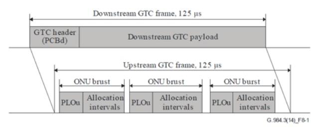
Each upstream GPON frame has a fixed duration of 125 s. Each uplink frame contains the data transported by one or more T-CONT / TCONT. All ONUs connected to a GPON port share the uplink bandwidth. All ONUs send their data upstream in their own time slots according to the requirements of the Bandwidth Map (BWmap). Each ONU reports the status of the data to be sent to the OLT using uplink frames. The OLT uses DBA to allocate upstream time slots to the ONUs and sends updates on each frame.
Note: Uplink frames are sent as bursts, which consist of the uplink physical layer overhead (PLOu) and one or more bandwidth allocation slots associated with a specific Alloc-ID.
As the picture shows, the difference between a descending and ascending frame.
Keywords
- Upstream physical layer overload (PLOu) - Overload of the physical layer uphill .
- Upstream OAM physical layer (PLOAMu) - PLOAM data messages in uphill . Think of it as a message-based operation and management channel between the OLT and the ONUs / ONTs.
- Up Power Level Sequence (PLSu) - Up Power Level Sequence.
- Report dynamic upstream bandwidth (DBRu) - Report upstream bandwidth dynamics .
- Payload : user data.
GPON technology functional blocks
OLT function blocks
An OLT consists of three main parts:
- Service port interface function - Provides translation between the service interfaces and the TC frame interface of the PON section.
- Functionality of brewing - Provides a communication path between the PON shell and the service shell, as well as patching functionality.
- Optical Distribution Network Interface (ODN) - Subdivided into two parts:
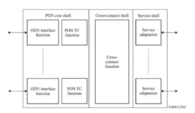
PON interface function
PON TC function - The Responsibilities include scoping, media access control, OAM, DBA, and Protocol Data Unit (PDU) delineation for the interconnect function and the management of the ONU.
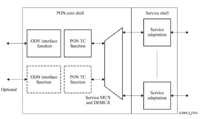
ONU / OLT function blocks
The functional blocks are similar to the OLT. In case the ONU / OLT works with only one PON interface (maximum 2 for protection purposes), the cross-connect function is omitted. Instead of this functionality, the MUX and DEMUX services are now responsible for the traffic.
Stacking protocol
The GPON protocol has its own stack, just Ethernet or IP. As shown in the image, this is the stacking protocol for GPON:
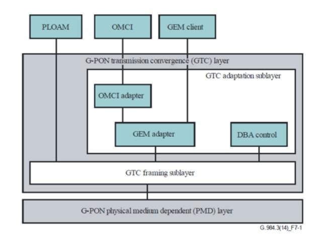
Keywords
- PMD layer - Equivalent to GPON interfaces found between OLTs and ONUs.
- GTC layer - Responsible for the encapsulation of payloads through the use of ATM cells or GEM frames. GEM frames can carry Ethernet, POTS, E1, and T1 cells.
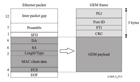
Traffic mapping: Ethernet
- It resolves Ethernet frames and maps Ethernet frame data directly to the GEM payload.
- GEM frameworks automatically encapsulate header information.
- 1: 1 alignment between an Ethernet frame and a GEM frame.
As shown in the image, an Ethernet frame is mapped to a GEM frame:
IMCO
ONU Management and Control Interface (OMCI) messages are used to discover ONTs / ONUs for management and control. These specialized messages are sent via dedicated GEM ports established between an OLT and an ONT / ONU.
The OMCI protocol allows an OLT to:
- Establish and release connections with the ONT.
- Manage the UNIs in the ONT.
- Request configuration information and performance statistics.
- Autonomous alerting of events, such as link failure.
Key points:
- The protocol goes through a GEM connection between OLT and ONT.
- GEM connection is established during ONT initialization.
- Protocol operation is asynchronous - OLT controller operates as master, ONT controller as slave.
Important techniques
Rank
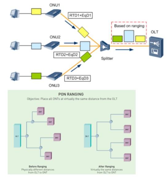
To avoid data conflicts (collisions), the OLT must be able to accurately measure the distance between itself and each ONU / ONT in order to provide an appropriate time interval for delivering data upstream. This allows ONUs to send data at specified time intervals to avoid upstream problems. This process is accomplished through a technique called rank.
Ranking process
The OLT initiates the process at a UN level when the UN first registers with the OLT and obtains the Round Trip Time (RTD) from the UN.
Based on the RTD, other key components are identified
Calculation of the physical range of this specific ONU, since this OLT requires an adequate equalization delay (EqD) for each ONU based on the physical range. RTC and EqD synchronize the data frames sent by all ONUs. As shown in the picture, a demonstration of what the process does, to place all ONUs / OLTs at the same virtual distance from the OLT.
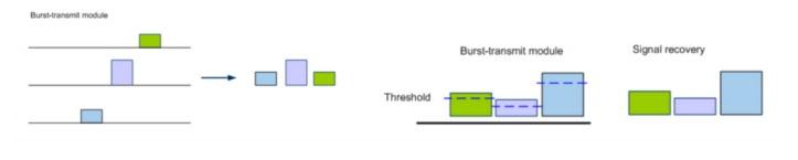
Burst technology
The upstream packet flow is burst, and each ONU / ONT is responsible for transmitting data in its assigned time slots. When an ONU / ONT is not within its time slot, the device disables transmission from its optical transceiver to avoid further ONU / ONT hits.
- Burst transmission function is supported by ONU / ONT modules.
- The burst reception function is compatible with OLT modules.
- The varying distance between each ONU / ONT and OLT results in attenuation of the optical signal. As a result, the power and level of the packets received by an OLT vary at different time intervals.
- Dynamic Threshold Adjustment allows the OLT to dynamically adjust the threshold for optical power levels. This ensures that all ONU signals can be recovered.
As shown in the picture, a demonstration of different data burst broadcast and then retrieved:
Dynamic Bandwidth Allocation (DBA)
DBA allows an OLT module to monitor PON network congestion in real time. This allows the OLT to adjust the bandwidth based on various factors including congestion, bandwidth usage, and configuration.
Key points of DBA
The DBA module integrated into the OLT continuously collects DBA reports, performs calculations and notifies the UNO via the BWMap field in the downstream frame. Due to the BWMap information, the ONU sends data upstream within the time slots allocated to occupy the upstream bandwidth. Bandwidth can also be allocated in static / fixed mode.
The use of the DBA allows
Improved upstream bandwidth usage on a PON port. Higher bandwidth for users and support for more users on a single PON port. Forward error correction (FEC). The transmission of digital signals can introduce bit errors and jitter, which can degrade the quality of signal transmission. GPON can take advantage of FEC, which allows the RX endpoint to check for error bits in the transmission.
Note: FEC is unidirectional and does not support error information comments.
Key points of the FEC:
- Does not require data retransmission.
- It supports FEC only in the downstream direction.
- Improved quality of PCBd transmission and payload processing.
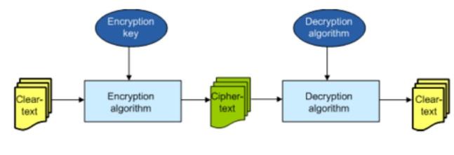
Line encryption
All downstream data is transmitted to all ONUs. One risk is that it is not allowed. ONUs receive downstream data for authorized ONUs. To combat this, GPON uses the AES128 algorithm to encrypt data packets.
Key Line Encryption Points
- Using line encryption does not increase overhead or decrease bandwidth usage.
- Using line encryption does not extend transmission times.
Key exchange and switching
- The OLT initiates a key exchange request to the UN. The UN responds to the request with a new key.
- After receiving the key, the OLT uses the new key to encrypt the data.
- The OLT sends the frame number that users of the new key send to the ONU.
- The ONU receives the frame number and switches the verification key on incoming data frames.
As shown in the image, the key exchange process:
Network protection modes in GPON technology
There are several types of network protection modes that GPON can use.
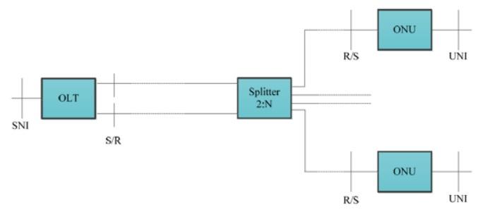
Type A
- It does not require an additional OLT PON port.
- When the primary fiber fails, services are transferred to the secondary fiber.
- The duration of the outage depends on the recovery time of the line.
- If the failure occurs on the separation line to the ONU, there is no backup.
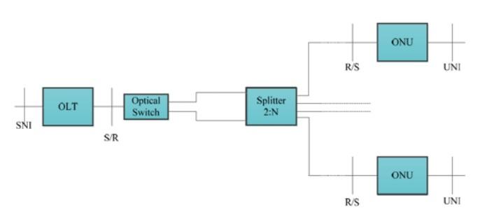
Type B
- OLT provides two GPON ports as valid and protective OLTs.
- Protection is limited to fiber from the OLT to the splitter and OLT cards.
- No equipment redundancy is foreseen on the ONU or the feed fibers.
- No full UN or ODN protection.
- It uses a 2 x N splitter and without any additional optical loss.
Type C
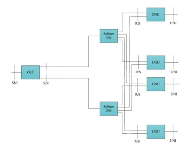
Redundancy for OLT, ODN and ONU (s)
- Provides 2 fully redundant links to subscriber facilities.
- Two options: 1 + 1 linear and 1: 1 linear protection.
1 + 1 protection:
- PON protection is dedicated to valid PONs.
- Normal traffic is copied and forwarded to both PONs, with a permanent bridge between the two OLTs.
- Traffic is sent to an ONU simultaneously, the selection between the two signals is based on predetermined criteria.
1: 1 protection:
- Normal traffic is routed over the valid or protection PON.
- The automatic protection switches between the PONs.
- More expensive, but offers maximum uptime.
Finally, notice that GPON technology is a telecommunications access technology which, as we have seen, uses optical fiber to reach the end customer. Its technical standards were approved in 2003-2004 by the ITU-T in recommendations G.984.1, G.984.2, G.984.3, G.984.4 and G.984.5. All OEMs must comply to ensure interoperability. These are the standardizations of PON networks at speeds greater than 1 Gbit / s. Two new recommendations were subsequently published: G.984.6 (Extension of the scope) and G.984.7 (Long scope). With all of this information, we hope you can now fully understand GPON technology.